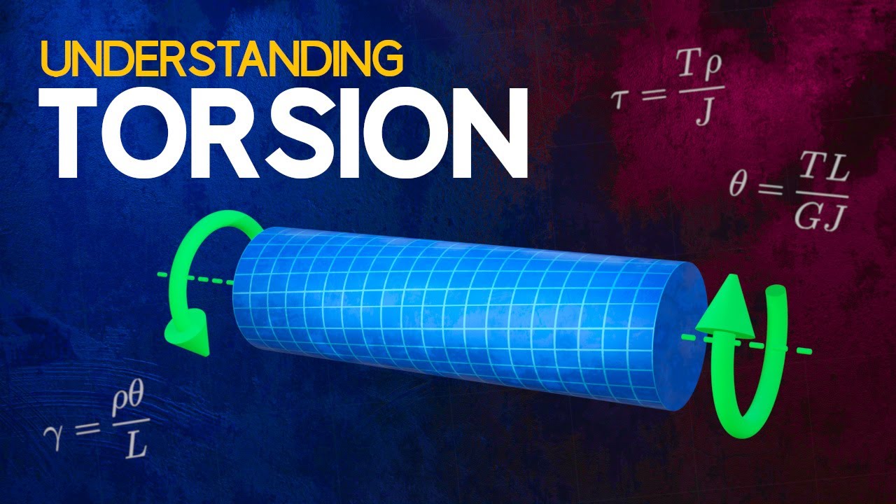
Torsion is the twisting of an object caused by a moment acting about its longitudinal axis. That moment is called torque. Torsional loading is an everyday engineering reality: drive shafts deliver engine power to wheels, wind turbine shafts carry blade torque to generators, and countless rotating components in machines experience twisting loads. This article explains how circular shafts respond to torque, how to calculate the resulting deformation and stresses, and why failure under torsion appears differently in ductile and brittle materials.
How a circular bar deforms under torsion
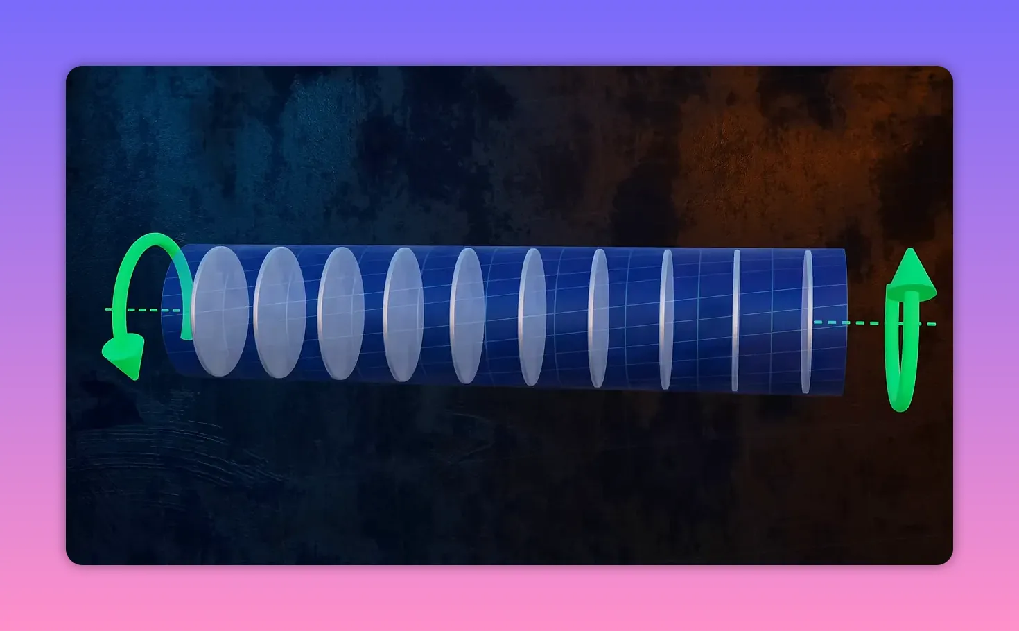
When a circular bar is subjected to torque, it twists along its length. Individual cross sections rotate relative to each other, but because the cross sections are axisymmetric, they do not distort. You can imagine the shaft as a stack of rigid discs that rotate slightly with respect to their neighbors. That convenient property makes circular shafts much simpler to analyze than non-axisymmetric sections such as rectangles, which exhibit complex warping under torsion.
Angle of twist
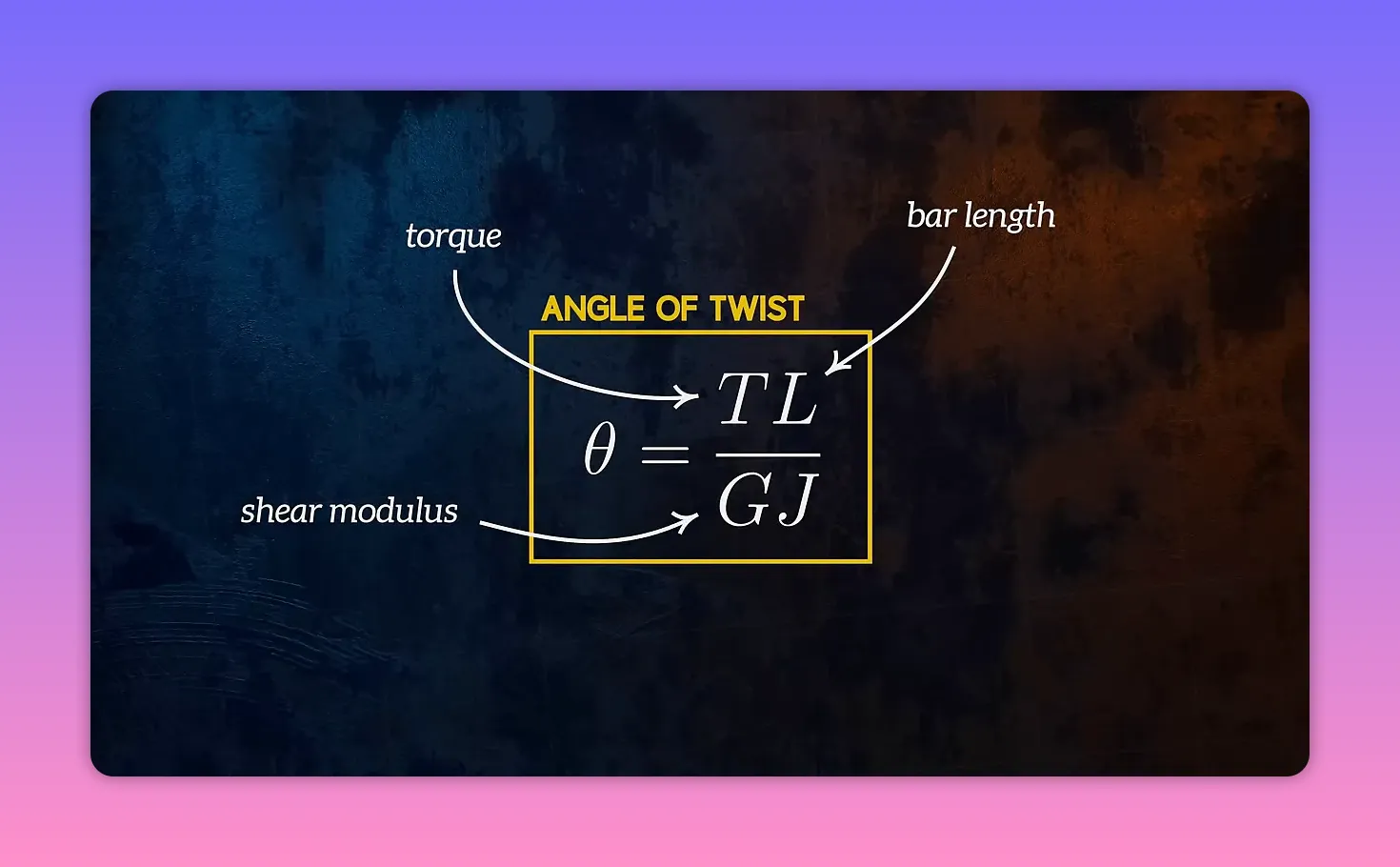
The rotation of the free end of a shaft relative to a fixed end is the angle of twist. For a uniform circular shaft of length L subject to a constant torque T, the angle of twist (often written theta or phi) is given by a simple relationship involving four parameters: The
- e applied torque
- L is the length of the shaft segment
- G is the shear modulus of the material
- J is the polar moment of inertia of the cross-section
The equation is: angle of twist = T L / (G J). This formula not only predicts how much a shaft will rotate under a load but also provides a way to measure the shear modulus G experimentally by applying a known torque to a specimen of known geometry and measuring the twist.
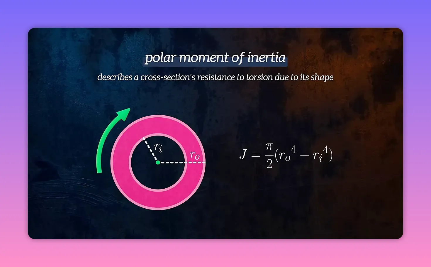
Polar moment of inertia
The polar moment of inertia J captures how the cross-sectional shape resists torsion. For a hollow circular shaft with outer radius Ro and inner radius Ri, the polar moment is:
J = (pi / 2) (Ro4 − Ri4)
Setting Ri = 0 yields the solid circular shaft value J = pi Ro4 / 2. Because J depends on radius to the fourth power, hollowing a shaft significantly increases torsional efficiency by placing more material where it counts most, away from the center.
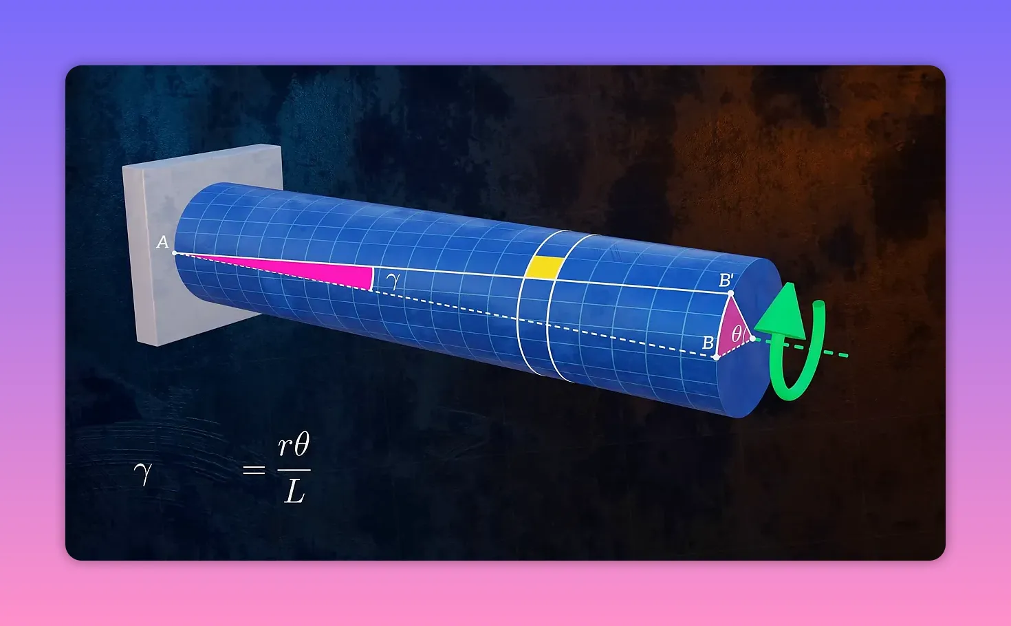
Shear strain in torsion
Torsion produces shear strains in the shaft. Consider a small longitudinal element at radius rho from the center. If the shaft twists by an angle theta over a length L, then the shear strain gamma at radius rho is given by geometry:
gamma = rho * theta / L
That expression shows shear strain varies linearly with radial distance. At the shaft surface (rho = outer radius), the shear strain is most significant. The derivation uses small-angle approximations and the arc length = radius times angle relationship, so this relationship applies to the usual engineering torsion cases.
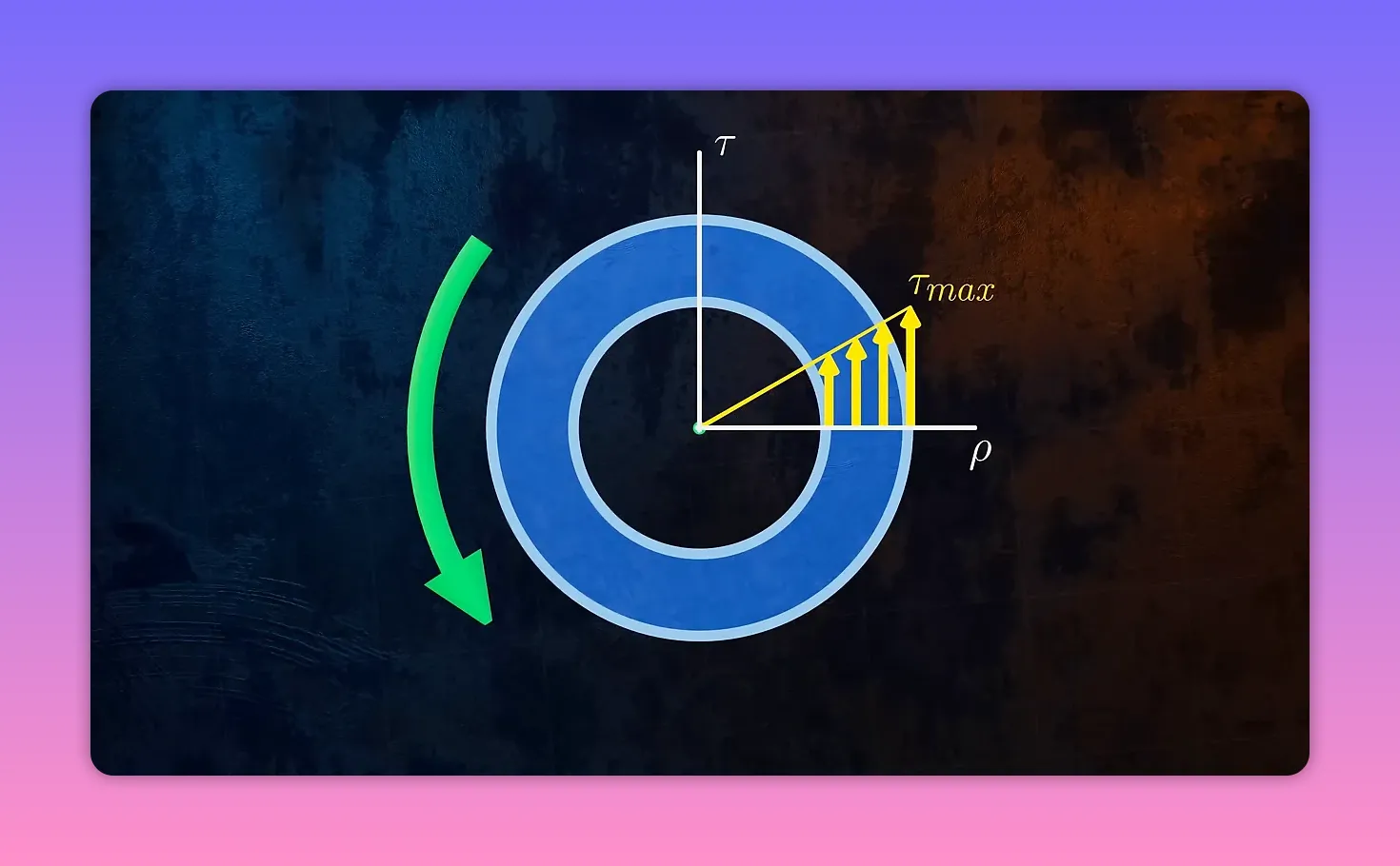
Shear stress distribution
Shear stress follows the same linear variation with radius as shear strain. By enforcing equilibrium — the sum of internal moment contributions from all differential area elements must equal the applied torque — you obtain the familiar formula:
tau(rho) = T * rho / J
The maximum shear stress occurs at the outer radius: tau_max = T * Ro / J. Because tau is proportional to rho, the central material of a solid shaft carries relatively little torsional load. That is why hollow shafts are more material efficient for transmitting torque and are commonly used where weight and stiffness matter.
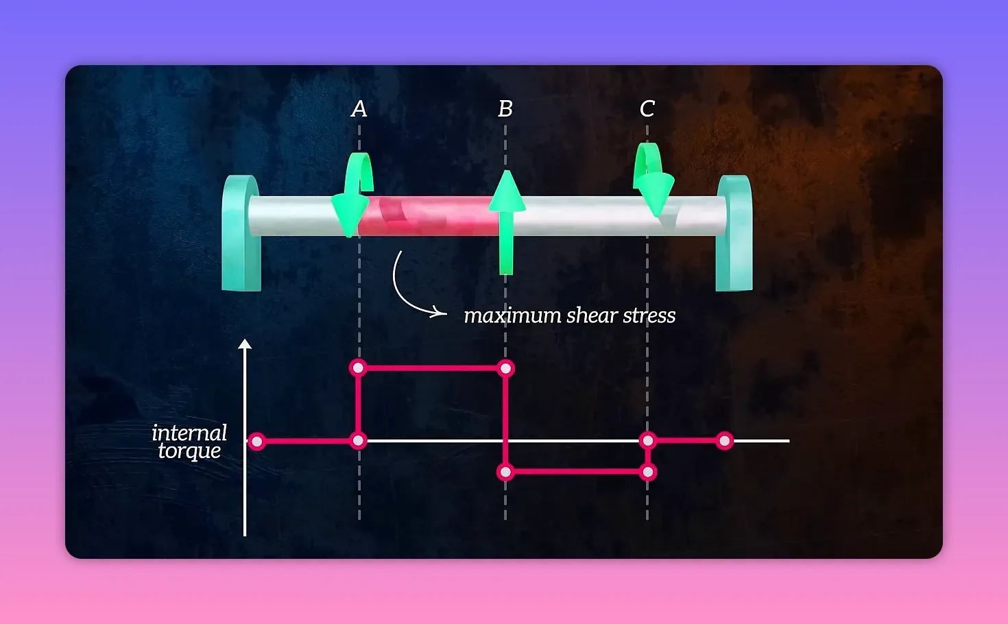
Internal torque diagrams for shafts with multiple loads
Shafts in machines are often subject to several applied torques at different points, such as gears, clutches, or couplings. To use the formulas above along the shaft, you first need the internal torque distribution. The procedure is analogous to finding shear force diagrams for beams:
- Draw a free-body diagram of the shaft with all applied torques and supports shown.
- Make imaginary cuts at segments of interest.
- Apply equilibrium to each cut to find the internal torque at that location.
Plotting the internal torque versus position produces the torque diagram. The section with the most significant internal torque determines the maximum shear stress using tau = T rho / J.
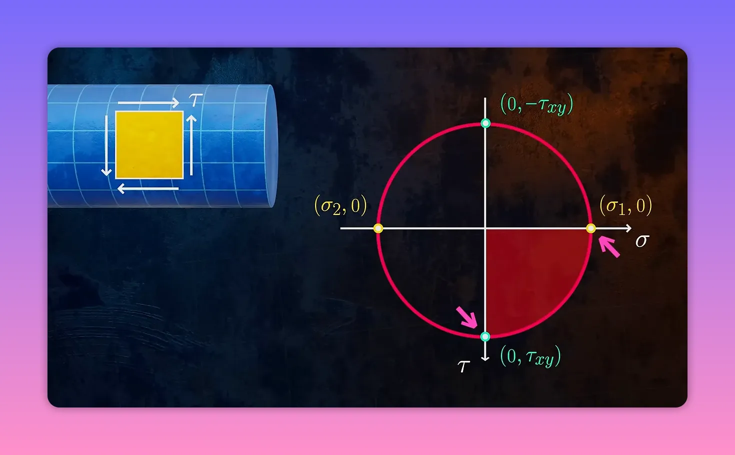
Torsional failure: ductile versus brittle
Failure under pure torsion depends on the material type. Two typical observations are:
- A ductile shaft tends to fail along the plane of maximum shear. The fracture appearance and orientation differ from those of a brittle fracture.
- A brittle shaft tends to fail along the plane of maximum tensile stress, which for pure torsion corresponds to an orientation rotated 45 degrees from the element where shear stress is highest.
Mohr’s circle for pure torsion helps visualize this. In one orientation, the element has zero everyday stress and maximum shear stress. Rotate the element by 45 degrees on Mohr’s circle, and everyday stresses appear and reach their maximum magnitude. Ductile materials typically fail at the point of maximum shear. Brittle materials, which are weaker in tension than in shear, fail where tensile everyday stresses are most significant. That geometric relationship explains why the fracture angles differ.
Key formulas at a glance
- Angle of twist theta = T L / (G J)
- Polar moment hollow circular: J = (pi / 2) (Ro4 − Ri4)
- Shear strain gamma(rho) = rho * theta / L
- Shear stress tau(rho) = T * rho / J
Practical takeaways
- For torsional stiffness and strength, use the polar moment of inertia J in design calculations. Increasing the adius dramatically increases torsional resistance.
- Hollow shafts are often preferable because they locate material at larger radii where it contributes most to J while reducing weight.
- Always compute the internal torque diagram for shafts with multiple applied torques before checking stresses and allowable limits.
- Consider material behavior: ductile and brittle components can show very different fracture appearances under identical torsional loading.
Understanding how torque, geometry, and material properties interact gives clear guidance for designing shafts that are both efficient and safe.


